Iranian Classification Society Rules

< Previous | Contents | Next >
Section 26 Fire Protection Materials
2601. Application
The requirements of this Section apply to tests and inspections for the approval of fire protection materials specified in Table 3.26.1 according to the requirements of Pt 8, Ch 1 of the Rules.
Table 3.26.1 Kinds and application of fire protection materials
Kinds | Application |
Non-combustible materials | (1) Non-combustible materials mean the materials defined in Pt 8, Ch 1, 103. of the Rules. (2) The kinds of test for non-combustible materials are to be the 'Test method for non-combustible material', the procedure of which is to be as specified in 2604. 1. of this Guidance. (3) The materials specified below are to be regraded as non-combustible materials for which no appro- val by the Society is required. (A) Sheet glass, glass rock, clay, ceramics, and glass fiber (B) Metals (except magnesium and magnesium alloys) (C) Sand, gravel, expanded vermiculite, slag (expanded or foam slag), diatomaceous earth, portland cement using pearlite or pumice as aggregates, gypsum, and magnesite concrete (D) Needle punched glass fiber products containing 2.5 % or less of lubricant |
"A" Class divi- sions | (1) "A" class divisions are the divisions defined in Pt 8, Ch 1, 103. of the Rules. They are used for bulkheads, decks, doors, cable penetrations, etc. (2) The kinds of test for “A” class divisions are to be “fire tests of A class divisions," the procedures of which are to be as specified in 2604. 2. (3) “A“ class divisions are classified into four ratings according to temperature conditions: ”A-60“ rat- ing, ”A-30“ rating, ”A-15“ rating and ”A-0“ rating. (4) The materials constituting “A” class divisions are all to be non-combustible materials specified in Par 2. In applying for approval, documents proving that the constituent materials are non-com- bustible (the certificate of the Society or the test results recognized by the Society) are to be sub- mitted in addition to the results of fire tests for the constituent materials. |
"B" Class divi- sions | (1) "B" class divisions are the divisions defined in Pt 8, Ch 1, 103. of the Rules. They are used for bulkheads, doors, continuous ceilings, cable penetrations, etc. (2) The kinds and procedure of tests for 'B' class divisions are to be “fire tests of B class divisions” the procedures of which are to be as specified in 2604. 2. (3) “B“ class divisions are classified into two ratings according to temperature condition: ”B-15“ rating and ”B-0“ rating. (4) The materials constituting “B” class divisions are to comply with the requirements specified in Par 2. In applying for approval, documents proving that the constituent materials are non-combustible (the certificate of the Society or the test results recognized by the Society) are to be submitted in addition to the results of fire tests for the constituent materials. |
Fire retardant base materials | (1) Fire retardant base materials are the combustible materials used for internal divisions, and lin- ings, draft stops, ceilings and their associated ground sills in corridors and stairway enclosures within accommodation and service spaces of a ship adopting Method ⅢC or ⅡC specified in Pt 8, Ch 3, 103. 5 of the Rules. (2) The kinds of test for fire retardant materials are to be test for surface flammability, smoke and toxicity test, the procedures of which are to be in accordance with the requirements specified in 2604. 3 and 4, respectively. |
Fire retardant veneers | (1) Fire retardant veneers are the combustible veneer materials applied on internal exposed surfaces and on the surfaces in consealed or inaccessible spaces in a ship except floor. (2) Fire retardant veneers applied on non-combustible bulkheads, linings, and ceilings within accom- modation spaces and service areas are to be not more than 2.5 mm in thickness. In corridors, stairway enclosures, and control stations, fire retardant veneers are to be not more than 1.5 mm in thickness. (3) Notwithstanding the requirements (2) above, if the calorific value of fire retardant veneers meas- ured by bomb method (refer to Appendix 1) does not exceed 45 MJ m , the limit of thickness specified in (2) may not be observed. (4) The kinds and test procedures are similar to those specified in 2604. 3 and 4. (5) In applying the requirements in (4) above for PVC films, test for surface flammability is to be conducted without insulation materials, and smoke and toxicity test is to be conducted including insulation materials. |
Guidance for Approval of Manufacturing Process and Type Approval, Etc. 2015 161
![]()
![]()
Table 3.26.1 Kinds and application of fire protection materials (continued)
Kinds | Application |
Fire retardant floor coverings | (1) Floor coverings are other layers in the floor construction above the deck plating except primary deck coverings. (2) The kinds of test for fire retardant floor coverings are to be test for surface flammability, smoke and toxicity test. The procedures of which are to be in accordance with the requirements specified in 2604. 3 and 4. |
Primary deck cov- erings | (1) Primary deck coverings are the first layer of a floor construction which is applied directly on top of the deck plating and is inclusive of any primary coat, anti-corrosive compound or adhe- sive which is necessary to provide protection or adhesion to the deck plating. (2) The kinds of test for the primary deck coverings are to be of the test for the primary deck coverings and the testing procedure is to be in accordance with the requirements specified in 2604. 4 and 5. |
Fire retardant coatings | (1) Fire retardant coatings are the finishing materials applied on the internal exposed surface of a ship. (2) The approval of fire retardant coatings is to be made to actual coating systems (combination of under coat and top coat) on the basis of the coatings classified according to the kinds of syn- thetic resins used. (3) The classes of fire retardant coatings are as follows : (A) Alkyd resin coating (B) Chlorinated rubber coating (C) Tar epoxy resin coating (D) Denatured epoxy resin coating (E) Pure epoxy resin coating (F) Urethane resin coating (G) Emulsion coating (H) Water gross coating (I) Poly-vinyl chloride resin coating (J) Pure silicone coating (K) Others (4) The kinds and test procedures are to be in accordance with 2604. 3 and 4 correspondingly. |
Vertically sup- ported textiles and films (including vertically hanging curtains and drap- eries) | (1) The test method for vertically supported textiles and films (including vertically hanging curtains and draperies) having the resistance to propagation of flame (hereinafter called curtains, etc.) is to be in accordance with the requirements in 2604. 6. (2) After flame time means the time during which the material continues to burn after the ignition source has been removed or extinguished. (3) Sustained ignition means after flame time of 5 seconds or more. (4) After glow means persistence of a material after cessation of flaming or after the ignition source has been removed. (5) Surface flash means the rapid flash of a flame across the surface pile finish and often leaving the base fabric in an essentially undamaged condition. |
Upholstered furni- ture | (1) The test method for upholstered furniture having the resistance to propagation of flame is to be in accordance with the requirements in 2604. 7. (2) Progressive smouldering is an exothermic oxidation not accompanied by flaming which is self-propagating, i.e. independent of the ignition source. It may or may not be accompanied by incandescence. |
Bedding compo- nents | (1) The test method for bedding components such as blankets, quilts, bedspreads, pillows and mat- tresses, including thin, light mattresses used on top of other mattresses having the resistance to propagation of flame is to be in accordance with the requirements in 2604. 8. (2) Mattress is product in the form of a resilient material (for instance, polyurethane foam or light fibre fill) or of padding materials in combination with steel springs (spring mattress), enveloped by a cover. (3) Quilt and pillow are products of padding materials (down/feather or textile fibre) enveloped by a textile fabric. (4) Ticking is fabric enveloping the resilient material in a mattress. (5) Ignitability is a measure of the ease with which a material or a product can be ignited so as to flame or progressively smoulder. (6) Ignition source is source of energy which is used to ignite combustible materials or products. (7) Flaming is undergoing combustion in the gaseous phase, usually with emission of light. (8) Smouldering is an exothermic reaction taking place in a material without flaming, with or with- out emission of light. (9) Progressive smouldering is smouldering which continues after the ignition source is ex- tinguished or removed. |
162 Guidance for Approval of Manufacturing Process and Type Approval, Etc. 2015
![]()
![]()
Table 3.26.1 Kinds and application of fire protection materials (continued)
Kinds | Application |
Fire door control system | The test method for control system of fire door which is required to be able to operate in case of fire is to be in accordance with the requirements in 2604. 9. |
2602. Data to be submitted
The following reference data are to be submitted to the Society in addition to those specified in
102.
(1) Kinds of materials (names and trade names of the materials specified in 2601. 1.
(2) Outline of testing facilities (This may be omitted if the tests are carried out by an organization which the Society considers appropriate for the purpose)
(3) Details of test specimen (including joint construction, points of temperature measurement, fixing
method of periphery, etc.)
2603. Type tests
1. The type tests are to be carried out by the procedures specified in 2604. or by those regarded to be equivalent by the Society in the presence of the Surveyor. The witness by the Surveyor may be omitted, however, if the type tests are conducted by any official organizations which the Society considers appropriate.
2. The test specified in the preceding 1 may be omitted if the material is subjected to the tests speci- fied in the preceding 1 in an organization which the Society considers appropriate and having a certificate or test records. The Society may require additional tests, however, if it considers necessary.
3. For other established test procedures and acceptance criteria other than those specified in 2604. the approval expiry period is as follows.
(1) The Society may issue type approval certificates of products tested in accordance with proce- dures adopted in IMO Res. 61(67), provided the tests were conducted no later than one year after entry into force of IMO Res. MSC 307(88).
(2) The Society may issue type approval of a product tested in accordance with procedures adopted in IMO Res. 61(67) without retesting, provided that the test report is not more than 15 years
old and that no alteration of components or construction has been made to the product.
2604. Test methods
1. Test method for non-combustible material
Test method for non-combustible material is to be in accordance with the requirements given in
Table 3.26.2. (refer to FTP Code, Annex 1, Part 1 and IMO Res. MSC 307(88) & ISO 1182)
Table 3.26.2 Test method for non-combustible material
Item | Requirements |
Test specimens | (A) The test specimen shall be taken from a sample which is sufficiently large to be representa- tive of the product. (B) The specimens are to be cylindrical and each is to have a diameter of 45 + 0 mm, a height of - 2 50 ± 3 mm and a volume of 80 ± 5 cm . (C) For homogeneous products, five specimens shall be made. For nonhomogeneous products, 10 specimens shall be made. |
Preparation of specimens | (A) If the thickness of the material is different from 50 ± 3 mm, specimens of the height of 50 ± 3 mm shall be made by using a sufficient number of layers of the material and/or by adjust- ment of the material thickness. (B) For non-homogeneous materials, the specimen of height of 50 ± 3 mm shall be constructed such that all layers are represented in the specimen in proportion to their presence, by vol- ume, in the original specimen. |
Guidance for Approval of Manufacturing Process and Type Approval, Etc. 2015 163
![]()
![]()
Table 3.26.2 Test method for non-combustible material (continued)
Item | Requirements |
Preparation of specimens | (C) The layers shall occupy a horizontal position in the specimen holder and shall be held togeth- er firmly, without significant compression, by means of two fine steel wires, of maximum di- ameter 0.5mm, to prevent air gaps between layers. The specimens of loose fill materials shall be representative in appearance, density, etc., as in use. (D) When a specimen is composed of a number of layers, the overall density should be as close as possible to that of the product provided by the manufacturer. |
Conditioning | The specimens are to be conditioned in a ventilated oven maintained at 60 ± 5 °C, for between 20 hours and 24 hours, and cooled to ambient temperature in a desiccator prior to the testing. The mass of each specimen is to be determined to an accuracy of 0.01 g prior to test. |
Observations during test | (A) Record the mass before and after test for each specimen tested and note any observations re- lating to the behaviour of the specimen during the test including during insertion into the apparatus. (B) Note the occurrence of any sustained flaming and record the duration of each flaming. Sustained flaming is to be taken as the continuous presence of flame caused by the specimen lasting 5 seconds or longer. (C) Some specimens exhibit only a steady blue-coloured luminous gas zone; this shall not be con- sidered as flaming but be noted under "observations during tes" in the test report. (D) Record the following temperatures, as measured by the thermocouples; (a) the initial furnace temperature, (furnace) : the average temperature over the final 10 min of the stabilization period) (b) the maximum furnace temperature (furnace) and the maximum specimen surface tem- perature (surface) : the discrete values at maximum temperature anywhere over the en- tire test period; and (c) the final furnace temperature (furnace) and the final specimen surface temperature (surface) : the average temperature over the final 1 min of the test period
|
164 Guidance for Approval of Manufacturing Process and Type Approval, Etc. 2015
![]()
![]()
Table 3.26.2 Test method for non-combustible material (continued)
Item | Requirements |
Expression of results | (A) Calculation of averages (a) For homogeneous products, calculate the averages for Mass loss(B) to Average temperature rise(E) for the five specimen. (b) For non-homogeneous products, calculate the averages for Mass loss(B) to Average tem- perature rise(E) for each set of five specimens in the same orientation. The results for each orientation shall be presented separately, but they shall not be combined. Classification shall be based on the most onerous orientation such that all the averages for each set of five specimens shall meet the requirements in "Classification of materials". (B) Mass loss (a) Calculate and record the mass loss in percentage for each of the five specimens, expressed as a percentage of the initial mass of the specimen, measured as specified in "Observations during test(A)". (b) Calculate the average mass loss in percentage, which is the average of mass loss of the five specimens. (C) Flaming (a) Calculate and record the total duration of sustained flaming, in seconds, for each of the five specimens measured as "Observations during test(B)". (b) Calculate the average duration of sustained flaming, which is the average of total duration of sustained flaming of the five specimens, (D) Temperature rise Calculate and record the following temperature rise in ℃ for each of the five specimens re- corded by the thermocouples as specified in "Observations during test(C)". (a) furnace temperature rise :
(b) specimen surface temperature rise :
(E) Average temperature rise |
Classification of materials | A material is to be deemed non-combustible if all the following criteria are satisfied. (A) The average furnace thermocouples temperature rise as calculated is not to exceed 30°C; (B) The average surface thermocouples temperature rise as calculated is not to exceed 30°C; (C) The mean duration of sustained flaming as calculated is not to exceed 10 second; and (D) The average mass loss as calculated is not to exceed 50 %. |
Others | Details of test for non-combustible materials not specially mentioned in 2604. 1 are to comply with FTP Code, Annex 1, Part 1. |
2. Fire test of “A” and “B” class divisions (refer to FTP Code, Annex
MSC 307(88))
(1) General
(A) The dimensions of the structural cores of the test specimens given
1, Part 3 and IMO Res.
in (2) below are intended
for structural cores of stiffened flat plates of steel or aluminium alloy. The Society may re- quire tests to be carried out on specimens having structural cores of materials other than
steel or aluminium alloy if such materials are more representative of the construction to be used on board ships.
(B) “A“ class divisions which consist of uninsulated steel bulkheads or decks of suitable scan-
tlings and without openings can be deemed to satisfy the requirements for ”A-0“ class divi- sions, i.e. to satisfy the requirements for the passage of smoke and flame, without the need for testing. All other divisions, including ”A-0“ class divisions with a structural core of alu- minium, are required to be tested.
(C) Results obtained on an insulating material used in conjunction with an 'A' class division may be applied to constructions incorporating heavier scantling than those tested and provid- ing the orientation of the construction is the same, i.e. results from bulkhead tests are not
to be applied to decks and vice versa.
(D) Constructions are to be tested without paint or other superimposed finish, provided that where they are only produced with a superimposed finish, and subject to the agreement of
Guidance for Approval of Manufacturing Process and Type Approval, Etc. 2015 165
![]()
![]()
the Society, they may be tested as produced. Such constructions may be required to be test- ed with a superimposed finish if such a finish is considered by the Society to have a detri- mental effect on the performance of the construction in the test.
(E) The construction to be tested are to be, as far as possible, representative of that to be used on board ships, including the materials and method of assembly.
(F) Non-combustible materials used in the construction of the specimen are not to be more than
24 months old from the date of the performance of the fire resistance test. If not, tests are to be conducted specified in 2604. 1 above.
(G) Adhesives used in A or B Class divisions should be low flame spread
(H) The thickness of insulation on the stiffeners need not be same as that of the steel plate.
(I) Doors, windows and other division penetrations intended to be installed in fire divisions made of material other than steel shall correspond to prototypes tested on a division made of such material.
(J) "B" class constructions shall be tested without finished. For constructions where this is not
possible, the finishes may be included in the "B" class test in the non-combustibility test of the construction.
(2) Nature of test specimens is to be as specified in Table 3.26.3.
specimen, and shall be included
166 Guidance for Approval of Manufacturing Process and Type Approval, Etc. 2015
![]()
![]()
Table 3.26.3 Fire test specimens of “A” and “B” class divisions
Kinds | Item | Requirements |
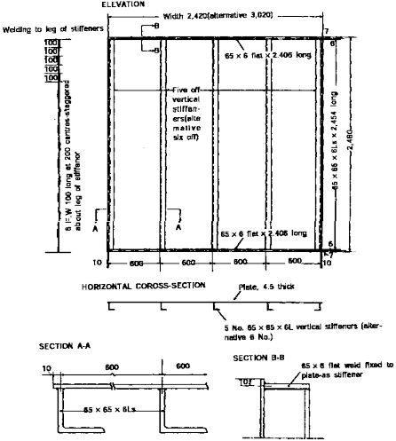
“A“ class bulkheads | Dimensions | (1) The minimum overall dimensions of test specimen, including the perimeter details at the top, bottom and vertical edges, are 2,440 mm width and 2,500 mm height. (a) When the maximum overall height in practice is less than that given above, then the test specimen shall be of the maximum height to be used in practice. (b) The minimum bulkhead panel height shall be a standard height of the manufactured panel with a dimension of 2,400 mm. (2) The overall dimensions of the structural core are to be 20 mm less in both the width and the height than the overall dimensions of the specimen, and the other dimensions of the structural core are to be as follows: - thickness of plating : steel 4.5 ± 0.5 mm aluminium 6.0 ± 0.5 mm - stiffeners spaced at 600 mm : steel 65 ± 5 mm × 65 ± 5 mm × 6 ± 1 mm aluminium 100 ± 5 mm × 75 ± 5 mm × 9 ± 1 mm (3) The width of the structural core may be greater than the specified dimensions providing that the additional width is in increments of 600 mm to maintain the stiffener centres and the relationship between the stiffeners and the perimeter detail. (4) Any joints in the plating are to be full welded, at least from one side. The dimensions of the structural core and the details around the perimeter of the speci- men are to be as illustrated in Fig 3.26.2 and Fig 3.26.3.
Fig 3.26.2 Structural Steel Core for "A" Class Bulkhead and "B" |
Guidance for Approval of Manufacturing Process and Type Approval, Etc. 2015 167
![]()
![]()
Table 3.26.3 Fire test specimens of “A” and “B” class divisions (continued)
Kinds | Item | Requirements |
“A“ class bulkheads | Dimensions |
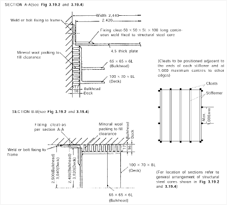
Fig 3.26.3 Connection between Restraint Frame and Structural Steel Core |
Construction | (1) Where insulation is provided by panels (e.g. a “B” class lining), then the test specimen is to be designed such that at least one of the panels is of full width and this, or these, are to be positioned such that both its/their longitudinal edges are jointed to an adjacent pan- el and are not secured to the restraint frame. (2) The overall dimensions of the panel insulation system, including the perimeter details at all the edges, are to be 20 mm greater in each direction than the equivalent dimensions of the structural core. | |
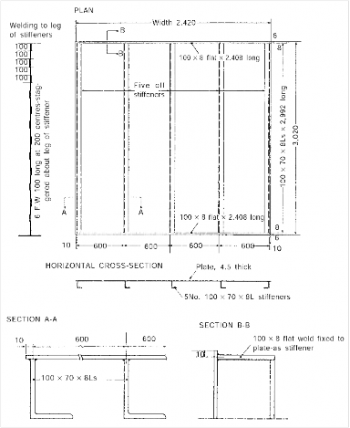
“A“ class decks | Dimensions | (1) The minimum overall dimensions of test specimen, including the perimeter details at all the edges, are 2,440 mm width and 3,040 mm length. (2) The overall dimensions of the structural core are to be 20 mm less in both the width and the length than the overall dimensions of the specimen, and the other dimensions of the structural core are to be as follows: - thickness of plating : steel 4.5 ± 0.5 mm aluminium 6.0 ± 0.5 mm - stiffeners spaced at 600 mm : steel 100 ± 5 mm × 70 ± 5 mm × 8 ± 1 mm aluminium 150 ± 5 mm × 100 ± 5 mm × 9 ± 1 mm (3) The width of the structural core may be greater than the specified dimensions providing that the additional width is in increments of 600 mm to maintain the stiffener centres and the relationship between the stiffeners and the perimeter detail. (4) Any joints in the plating are to be full welded, at least from one side. The dimensions of the structural core and the details around the perimeter of the speci- men are to be as illustrated in Fig 3.26.3 and Fig 3.26.4. |
168 Guidance for Approval of Manufacturing Process and Type Approval, Etc. 2015
![]()
![]()
Table 3.26.3 Fire test specimens of “A” and “B” class divisions (continued)
Kinds | Item | Requirements |
“A“ class decks | Dimensions |
Fig 3.26.4 Structural Steel Core for "A" Class Deck and "B" Class Ceiling |
Construction | (1) Where insulation is provided by panels (e.g. a “B” class ceiling), then the test specimen is to be designed such that at least one of the panels is of full width and this, or these, are to be positioned such that both its/their longitudinal edges are jointed to an adjacent pan- el and are not secured to the restraint frame. (2) The overall dimensions of the panel insulation system, including the perimeter details at all the edges, are to be 20 mm greater in each direction than the equivalent dimensions of the structural core. | |
“A“ class doors | Dimensions | The test specimen is to incorporate the maximum size (in terms of both the width and the height) of door leaf of leaves for which approval is to be sought. The maximum size of a door which can be tested will be determined by the requirement to retain certain dimensions of the structural core. |
Design | (1) Door furniture such as hinges, locks, latches, shoot bolts, handles, etc. are to be con- structed of materials having melting points of not less than 950°C unless it can be shown by the fire test that materials having melting points below 950°C do not adversely affect the performance of the door. (2) The door leaf and frame are to be mounted as appropriate into a 'A' class bulkhead of compatible construction, thereby reflecting an actual end use situation. The bulkhead is to have dimension as specified in the dimension of 'A' class bulkhead above. The bulkhead is to be of a construction approved by the Society as having at least a similar classi- fication to that required by the door. |
Guidance for Approval of Manufacturing Process and Type Approval, Etc. 2015 169
![]()
![]()
Table 3.26.3 Fire test specimens of “A” and “B” class divisions (continued)
Kinds | Item | Requirements |
“A“ class doors | Design | No additional stiffening shall be provided to the structurual core unless provided as part of the door frame. The method of fixing the door frame to the bulkhead is to be as used in practice. The door is to be positioned such that there is a minimum width of the bulkhead of 300 mm to each vertical side of the door and a minimum distance of 100 mm from the top edge of the bulkhead. If the method of fixing the door frame in a test is made by bolts, the Society may also accept welding as a method of fixing the door frame without further tests. (3) The door is to be positioned such that there is a minimum width of the bulkhead of 300 mm to each vertical side of the door and a minimum distance of 100 mm from the top edge of the bulkhead. If the method of fixing the door frame in a test is made by bolts, the Society may also accept welding as a method of fixing the door frame without fur- ther tests. (4) For doors mounted in a three-sided frame, the door shall be mounted with a bottom gap of between 12 mm and 25 mm between the bottom of the door and the test frame. (5) The door is to be mounted into the bulkhead such that the side expected to give the in- ferior performance will be exposed to the heating condition of the test. A hinged door is to be tested with the door leaf opening away from the heating conditions unless the Society deems otherwise. For sliding doors, it is not possible to state generally from which side the door is to be tested to give the inferior performance. It will, therefore, be necessary to conduct two separate tests, one with the door mounted to the exposed face and one with the door mounted to the unexposed face of the bulkhead (6) For a door which incorporates a ventilation opening within its construction, the ventilation grille(s) is (are) to be open at the commencement of the test. Temperature measurements on such a door are not to be made over the face of the grille(s). (7) Lift landing doors can be expected to be exposed to fire from the corridor side only, and they shall be exposed to fire test heating conditions from that side only. (8) Tests performed with double leaf doors will not be accepted as approval documentation for single leaf doors. (9) Double leaf doors should be tested with equally sized door leaves unless the door is in- tended to have unequally sized leaves. |
“B“ class bulkheads | Dimensions | (1) The minimum overall dimensions of test specimen, including the perimeter details at the top, bottom and vertical edges, are 2,440 mm width and 2,500 mm height. When the max- imum overall height in practice is to be less than given above, then the test specimen is to be of the maximum height to be used in practice. (2) The minimum bulkhead panel height shall be a standard height of the manufactured panel with a dimension of 2,400 mm. |
Construction | Where the construction incorporates panels, the specimen is to be constructed such that at least one of the panels is of full width and this, or these, is to be positioned such that both its/their longitudinal edges are jointed to an adjacent panel and are not secured to the restraint frame. | |
“B“ class decks | Dimensions | The minimum overall dimensions of test specimen, including the perimeter details at all the edges, are 2,440 mm width and 3,040 mm length. When the maximum dimension in practice is to be less than given above, then the test specimen is to be of the maximum size to be used in practice. |
Construction | Where the construction incorporates panels, the specimen is to be constructed such that at least one of the panels is of full width and this, or these, is to be positioned such that both its/their longitudinal edges are jointed to an adjacent panel and are not secured to the restraint frame. | |
“B“ class door | Dimensions | The test specimen is to incorporate the maximum size (in terms of both the width and the height) of door leaf of leaves for which approval is to be sought. The maximum size of a door which can be tested will be determined by the requirement to retain certain dimensions of the bulkhead. |
Design | (1) Door furniture such as hinges, locks, latches, shoot bolts, handles, etc. are to be con- structed of materials having melting points of not less than 850°C unless it can be shown by the fire test that materials having melting points below 850°C do not adversely affect the performance of the door. (2) The door leaf and frame are to be mounted as appropriate into a 'B' class bulkhead of compatible construction, thereby reflecting an actual end use situation. The bulkhead is to have dimension as specified in the dimension of 'B' class bulkhead above. The bulkhead is to be of a construction approved by the Society as having at least a similar classi- fication to that required by the door. The method of fixing the door frame to the bulk- head is to be as used in practice. |
170 Guidance for Approval of Manufacturing Process and Type Approval, Etc. 2015
![]()
![]()
Table 3.26.3 Fire test specimens of “A” and “B” class divisions (continued)
Kinds | Item | Requirements |
“B“ class door | Design | (3) The bulkhead shall be of a construction approved by the Society as having at least a sim- ilar classification to that required by the door, and approval shall be limited to the type of construction in which the door was tested. (4) The method of fixing the door frame to the bulkhead shall be as used in practice. If the method of fixing the door frame in a test is made by bolts, the Society may also accept welding as a method of fixing the door frame without further tests. (5) For doors mounted in a three-sided frame, the door shall be mounted with a bottom gap of between 12 mm and 25 mm between the bottom of the door and the test frame. (6) The door is to be positioned such that there is a minimum width of the bulkhead of 300 mm to each vertical side of the door and a minimum distance of 100 mm from the top edge of the bulkhead. (7) The door is to be mounted into the bulkhead such that the side expected to give the in- ferior performance will be exposed to the heating condition of the test. A hinged door is to be tested with the door leaf opening away from the heating conditions unless the Society deems otherwise. For sliding doors, it is not possible to state generally from which side the door is to be tested to give the inferior performance. It will, therefore, be necessary to conduct two separate tests, one with the door mounted to the exposed face and one with the door mounted to the unexposed face of the bulkhead (8) For a door which incorporates a ventilation opening within its construction, the ventilation grille(s) is (are) to be open at the commencement of the test. Temperature measurements on such a door are not to be made over the face of the grille(s). |
“B“ class linings | Dimensions | (1) The minimum overall dimensions of test specimen, including the perimeter details at the top, bottom and vertical edges, are 2,440 mm width and 2,500 mm height. When the max- imum overall height in practice is to be less than that given above, then the test speci- men shall be of the maximum height to be used in practice. (2) The minimum bulkhead panel height shall be a standard height of the manufactured panel with a dimension of 2,400 mm. |
Design | (1) The lining is to be positioned alongside a structural core constructed in accordance with the dimension of 'A' class bulkhead above. The design of the lining is to be such that it facilitates its assembly with the limited access provided by the proximity of the structural core, i.e. it is to be mounted with the structural core in place. (2) During a test on an “A” class bulkhead which utilizes membrane protection along its ex- posed side, e.g. a 'B' class lining, it is possible also to evaluate the performance of the lining with a view to classification providing that the necessary thermocouples are at- tached to the lining and proving that the necessary integrity measurements are made. (3) The specimen is to be constructed such that at least one of the panels is of full width and this, or these, is to be positioned such that both its/their longitudinal edges are joint- ed to an adjacent panel and are not secured to the restraint frame. | |
“B“ class ceilings | Dimensions | (1) The minimum overall dimensions of test specimen, including the perimeter details at the top, bottom and vertical edges, are 2,440 mm width and 3,040 mm length. (2) When the maximum dimensions in practice are less than those given above then the test specimen shall be of the maximum size to be used in practice, and the tested width shall be reported. |
Design | (1) The ceiling is to be positioned below a structural core constructed in accordance with the dimension of 'A' class deck above. (2) The design of the ceiling is to be such that it facilitates its assembly with the limited ac- cess provided by the proximity of the structural core, i.e. it is to be mounted with the structural core in place. (3) During a test on an “A” class deck which utilizes membrane protection along its under- side, e.g. a 'B' class ceiling, it is possible also to evaluate the performance of the ceiling with a view to classification providing that the necessary thermocouples are attached to the ceiling and proving that the necessary integrity measurements are made. (4) If the ceiling incorporates panels, the specimen is to include example of both the lateral and longitudinal joints between the panels. (5) If the specimen is to simulate a ceiling where the maximum length of the panels is great- er than the length of the specimen, then a joint is to be positioned at a distance of ap- proximately 600 mm from one of the shorter ends of the test specimen. (6) The specimen is to be constructed such that at least one of the panels is of full width and this, or these, is to be positioned such that both its/their longitudinal edges are joint- ed to an adjacent panel and are not secured to the restraint frame. |
Guidance for Approval of Manufacturing Process and Type Approval, Etc. 2015 171
![]()
![]()
Table 3.26.3 Fire test specimens of “A” and “B” class divisions (continued)
Kinds | Item | Requirements |
Windows | General | Window is taken to include windows, sidescuttles and any other glazed opening provided for light transmission or vision purposes in “A” class bulkheads. Windows in “A” class doors are considered to be part of the door and they are to be tested within the appropriate door. |
Dimensions | (1) The test is to be conducted on the window of the maximum size (in terms of both the width and the height) for which approval is sought. (2) The test shall be conducted on a window of the maximum size(in terms of both the height and the width) and the type of the glass pane and/or the minimum thickness of the glass pane or panes/and gaps, if appropriate, for which approval is sought. Test re- sults obtained on this configuration shall, by analogy, allow approval of windows of the same type, with lesser dimensions in terms of height and width and with the same or greater thickness. | |
Design | The bulkhead which includes the window is to be insulated to class 'A-60' on the stiffened face, which is to be the face exposed to the heating conditions of the test. There may be special applications of windows where the Society considers it appropriate to test the window with the insulation of the bulkhead to the unexposed face of the structural core, or within bulkheads other than class 'A-60'. The window is to be positioned within the bulkhead, shown in Fig 3.26.2, at that height which is intended for practical application. When this is not known, the window is to be positioned with the top of its frame as close as possible, but not closer than 300 mm, to the top of the bulkhead. | |
Fire dampers | Dimensions | The maximum sizes (in terms of both the width and the height, or the diameter) of each type of fire damper for which approval is sought are to be tested in both vertical and horizontal orientation. |
Design | (1) A bulkhead which includes the damper is to be constructed in accordance with the di- mension of 'A' class bulkhead above and is to be insulated to class “A-60” on the stiff- ened face, which is to be the face which is not exposed to the heating conditions of the test. A deck which includes the damper is to be constructed in accordance with (B) (a) above and is to be insulated to class “A-60” on the stiffened face, which is to be the face which is exposed to the heating conditions of the test. (2) Fire dampers are to be incorporated into or fixed to coaming or spigots, which are to be welded or bolted into the structural core. The length on the unexposed side = (450 mm or a needed insulation length for a damper under test)(Lunexp)+ 50 mm. The thickness of the coaming or spigot shall be as follows : * Width means the greater of the two cross-sectional dimensions. For widths or diameters of ducts in excess of 300 mm but less than 760 mm, the thick- ness of the coaming or spigot is to be obtained by interpolation. The coaming or spigot are to be insulated as shown in Fig 3.26.5. (3) The coamings or spigots (including insulation) are to be positioned only in the top half of a bulkhead but are to be no closer than 200 mm from the edges of a bulkhead or a deck. Where more than one damper is to be tested simultaneously in a division, the sepa- ration between adjacent coamings or spigots (including insulation) are not to be less than 200 mm. When more than one damper is included in a bulkhead, the top edges of all dampers are to be, as far as possible, at the same height. (4) The fire dampers are to be positioned on the exposed face of the bulkhead or deck, at a distance of at least 225 mm from the structural core, with their operative controls also on that side of the division. When a damper is mounted in the bulkhead the fuse element should be situated at the lowest level of the damper as in practice (5) Fire dampers which are operated automatically shall be in the open position at the start of the test and shall be closed by an automatic device. The damper shall be in the closed position within 2 min after the commencement of the test. If the fire damper fails to close after 2 min from the start of the test, the fire damper shall be deemed to have failed and the test shall be discontinued. |
Width* or diameter of the duct | Minimum thickness of coaming or spigot |
Up to and including 300 mm | 3 mm |
760 mm and over | 5 mm |
172 Guidance for Approval of Manufacturing Process and Type Approval, Etc. 2015
![]()
![]()
Table 3.26.3 Fire test specimens of “A” and “B” class divisions (continued)
Kinds | Item | Requirements |
Fire dampers | Design |
Fig 3.26.5 Fire Dampers: Insulation on Test Specimens and Position of Unexposed-face Thermocouples (6) Fire dampers which are operated with a manual systems shall be closed at the test time of 1 min. |
Pipe and duct penetrations | Dimensions | The maximum and minimum sizes (in terms of both the width and the height, or diameter) of each type of pipe penetration for which approval is sought are to be tested in both vertical and horizontal orientation. |
Design | (1) A bulkhead which includes the pipe penetration is to be constructed in accordance with (A) (a) above and is to be insulated to class “A-60” on the stiffened face, which is to be the face which is not exposed to the heating conditions of the test. A deck which in- cludes the pipe penetration is to be constructed in accordance with the dimension of 'A' class deck above and is to be insulated to class “A-60” on the stiffened face, which is to be the face which is exposed to the heating conditions of the test. (a) "A-0" class pipe penetrations are recommended to be performed in an uninsulated ("A-0") bulkhead/deck. If the pipe penetrations are tested as an "A-60" class penetrations, any in- sulation fitted (on the penetration itself and 200 mm around) will be required to be fitted also for class "A-0". |
Guidance for Approval of Manufacturing Process and Type Approval, Etc. 2015 173
![]()
![]()
Table 3.26.3 Fire test specimens of “A” and “B” class divisions (continued)
Kinds | Item | Requirements |
Pipe and duct penetrations | Design | (2) The pipe penetrations are to be positioned only in the top half of a bulkhead but are not to be closer than 200 mm from the edges of a bulkhead or a deck. Where more than one pipe penetration is to be tested simultaneously in a division, the separation between ad- jacent penetrations is not to be less than 200 mm. Both measurements are to relate to the distance to the nearest part of the penetration system, including any insulation which is part of the system. (3) Each pipe passing through a penetration is to project 500 ± 50 mm beyond the exposed end of the penetration and 500 ± 50 mm beyond the unexposed end of the penetration. The exposed end of the pipe is to be blanked off, using an appropriate methodology to ensure that any fire penetration into the pipe does not occur via the end of the pipe in advance of it occurring through the exposed perimeter of the pipe. (4) Each pipe is to be firmly supported and fixed independent of the bulkhead or deck on the unexposed side of the test specimen, e.g. by a framework mounted from the restraint frame. The support and fixing of the pipe are to restrain it from movement during the test. (5) When the deck penetration is fitted on an exposed side or is fitted symmetrically, general application will be given. When the deck penetration is fitted on an unexposed side, the approval will limit the penetration to the tested orientation. When the bulkhead penetration is fitted symmetrically, approval would be given for general application. For bulkhead pen- etrations with an exposed or unexposed fitted frame, one test for each fitting is required in order for obtaining approval for general application. (6) Sealing of pipe and duct penetrations: there shall be no visible openings before the start of the fire test. |
Cable transits | Dimensions | The maximum and minimum sizes (in terms of both the width and the height, or diameter) of each type of pipe penetration for which approval is sought are to be tested in both vertical and horizontal orientation. |
Design | (1) A bulkhead which includes the cable transit is to be constructed in accordance with the dimension of 'A' class bulkhead above and is to be insulated to class “A-60” on the stiff- ened face, which is to be the face which is not exposed to the heating conditions of the test. A deck which includes the cable transit is to be constructed in accordance with the dimension of 'A' class deck above and is to be insulated to class 'A-60' on the stiffened face, which is to be the face which is exposed to the heating conditions of the test. (a) "A-0" class cable transits are recommended to be performed in an uninsulated ("A-0") bulkhead/deck. If the cable transits are tested as an "A-60" class penetrations, any in- sulation fitted (on the cable transits itself and 200 mm around) will be required to be fit- ted also for class "A-0". (2) The cable transits are to be positioned only in the top half of a bulkhead but are not to be closer than 200 mm from the edges of a bulkhead or a deck. Where more than one cable transit is to be tested simultaneously in a division, the separation between adjacent penetrations is not to be less than 200 mm. Both measurements are to relate to the dis- tance to the nearest part of the penetration system, including any insulation which is part of the system. (3) Notwithstanding the above, the distance between transits is to be sufficient to ensure that the transits do not influence each other during the test, except that this requirement does not apply to muli-transits which are intended to be positioned adjacent to one another. (4) The cables are to project 500 ± 50 mm beyond the transit on the exposed side of the divi- sion and 500 ± 50 mm on the unexposed side. Each cable shall be firmly supported and fixed independent of the bulkhead or deck on the unexposed side of the test specimen, e.g., by a framework mounted from the restraint frame. The support and fixing of the ca- bles shall restrain them from movement during the test. (5) Cable transits shall be fitted to the bulkhead or deck in accordance with the manufactur- er's specifications. The cables and sealing compounds or blocks shall be incorporated into the transits with the bulkhead and deck panels places respectively in vertical and horizon- tal positions. Any insulation shall be applied to the cables and transits with the panels in the same respective positions. (6) The transit(s) is to be tested incorporating a range of different types of cables (e.g. in terms of number and type of conductor, type of sheathing, type of insulation material, size) and is to provide an assembly which represents a practical situation which may be found on ships. The test results obtained from a given configuration are generally valid for the tested types of cables of size equal to or smaller than tested. |
174 Guidance for Approval of Manufacturing Process and Type Approval, Etc. 2015
![]()
![]()
Table 3.26.3 Fire test specimens of “A” and “B” class divisions (continued)
Kinds | Item | Requirements |
Cable transits | Design | (7) Tests shall be conducted for the maximum and minimum fill based on the inside cross- sectional area at each transit. The distance between the adjacent cables shall be the minimum specified by the manufacturer, and the cables should be placed close to the centre of the transit. (8) When the deck cable transit is fitted on an exposed side or is fitted symmetrically, gen- eral application will be given. When the deck cable transit is fitted on the unexposed side, the approval will limit the penetration to the tested orientation. When the bulkhead cable transit is fitted symmetrically, approval would be given for general application. For bulkhead cable transit with exposed or unexposed fitted frame, one test for each fitting is required in order for obtaining approval for general application. (9) Sealing of cable transits shall have no visible opening before the start of the fire test. |
Continuous “B“ class divisions | Continuous 'B' class ceilings | The ceilings are to be tested in accordance with “B“ class ceilings above except that the ceil- ing is to be mounted on the horizontal furnace so that at least 150 mm high “B” class bulk- heads are mounted on the furnace and the ceiling is fixed to these partial bulkheads by using the joining method as is intended to be used in practice. Such ceilings and the joining meth- ods are to be evaluated as required for ceilings in accordance with “B“ class ceilings above and accordingly they are to be classified as “continuous ”B“ class ceilings”. |
Continuous “B” class linings | A lining which has been evaluated in accordance with “B“ class linings above to be a “B” (“B- 0”, “B-15”, as applicable on basis of the lining test) class lining may be considered form- ing 'continuous “B” (“B-0” or “B-15”, as applicable) class lining' in conjunction with a 'con- tinuous “B” (“B-0' or ”B-15“, as applicable) class ceiling' and with the joining method used in the test without further testing the lining. | |
Continuous “B” class construction | An enclosed construction installed on an “A” class deck and formed by 'continuous “B” (“B- 0” or “B-15”, as applicable) class lining' and 'continuous “B”(“B-0” or “B-15”,as appli- cable) class ceiling' is to be considered forming 'continuous 'B' class construction“. |
(3) Examination of the test specimens
(A) The Society is to verify the conformity of the test specimen with the drawings and method of assembly provided by the applicant and any area of discrepancy is to be resolved prior
to commencement of the test.
(B) Door clearances
Following mounting of the door and immediately prior to test, the Society is to measure the actual clearances between the door leaf and the doorframe, and additionally for a double leaf door between the adjacent door leaves. The clearances are to be measured for each door leaf at two positions along the top and bottom edges and at three positions along each vertical edge.
(C) Door operation
Similarly, immediately prior to test, the Society is to check the operability of the door by opening the door leaf by a distance of at least 300 mm. The door leaf is to then be closed, either automatically, if such a closing device is provide, or manually. The door may be latched for the test but is not to be locked, and no devices for latching or locking are to be included which are not normally incorporated in practice.
(4) Observations during the test
Observations during the test is to be as specified in Table 3.26.4.
Table 3.26.4. Observation of “A” and “B” class divisions
Item | Observation |
Flaming on unexposed face | The occurrence and duration of any flaming on the unexposed surface, together with the loca- tion of the flaming, are to be recorded. In case where it is difficult to identify whether or not there are flames then the cotton-wool pad is to be applied to the area of such disputed flam- ing to establish whether ignition of the pad can be initiated. |
Guidance for Approval of Manufacturing Process and Type Approval, Etc. 2015 175
![]()
![]()
Table 3.26.4 Observation of “A” and “B” class divisions (continued)
Item | Observation |
Cotton-wool pad | (a) Tests with the cotton-wool pad are used to indicate whether cracks and openings in the test specimen are such that they could lead to the passage of hot gases sufficient to cause ignition of combustible materials. (b) A cotton-wool pad is employed by placing the frame within which it is mounted against the surface of the test specimen, adjacent to the opening or flaming under examination, for a period of 30 seconds, or until ignition (defined as glowing or flaming ) of the cot- ton- wool pad occurs (if this happens before the elapse of the 30 seconds period). A cot- ton- wool pad is to be used only once. |
Gap gauges | (a) Tests with the gap gauges are used to indicate whether cracks and openings in the test specimen are of such dimensions that they could lead to the passage of hot gases suffi- cient to cause ignition of combustible materials. (b) The gap gauges are to be used at intervals which will be determined by the apparent rate of the specimen deterioration. Two gap gauges are to be employed, in turn, and without undue force to determine: - whether the 6 mm gap gauge can be passed through the specimen such that the gauge projects into the furnace, and can be moved a distance of 150 mm along the gap, or - whether the 25 mm gap gauge can be passed through the specimen such that the gauge projects into the surface. (c) If gaps in "A" or "B" class divisions are fully or partly sealed by intumescent materials, the gap gauge test shall be performed as if no intumescent material is present. (d) For doors mounted in a three-sided frame, the change of gap at the bottom of the door as measured by a horizontally-held gap gauge shall not increase by more than 12 mm along the bottom edge of the door. 12 mm gap gauge can be used for the purpose of ex- amining the increase of such gap. The edges of the door above the horizontal plane along the bottom of the door should be checked in the same manner as the fou-sided framed door. * If the door is mounted with a 13 mm gap, the 25 mm gap gauge may be used to de- termine an unacceptable change in gap. |
Deformation | The deflection of an “A” or "B" class test specimen, and additionally in the case of a door the maximum displacement of each corner of the door leaf relative to the door frame, are to be recorded during the test. These deflections are to be measured with an accuracy of 2 mm . |
General behaviour | If quantities of smoke are emitted from the unexposed face, this is to be noted in the report. |
(5) Duration of testing
Kind | Duration of testing |
“A” class divisions | For all “A” class divisions, including those with doors, the test is to continue for minimum 60 minutes. When the specimen is of an “A” class division, with a structural steel core which is imperforate (e.g. without door), and where insulation is provided to the exposed face only (i.e. the structural steel core is the unexposed face of the construction), it is permitted to ter- minate the test prior to 60 minutes once the unexposed face temperature rise limits have been exceeded. |
“B“ class divisions | For all “B” class divisions, including those with doors, the test is to continue for minimum 30 minutes. |
Termination of the test | The test may be terminated for one or more of the following reasons : (1) safety of personnel or impending damage to equipment ; (2) attainment of selected criteria ; or (3) request of the sponsor. The test may be continued after failure under subparagraph (2) above to obtain additional data. |
Duration of testing is to be as specified in Table 3.26.5. Table 3.26.5 Duration of testing of “A” and “B” class divisions
176 Guidance for Approval of Manufacturing Process and Type Approval, Etc. 2015
![]()
![]()
(6) Performance criteria
Performance criteria is to be as specified in Table 3.26.6.
Table 3.26.6 Performance criteria of “A” and “B” class divisions (continued)
Item | Kind | Performance criteria |
Insulation | “A” class divisions, including “A” class doors | The average unexposed face temperature rise is not to be more than 140 °C, and the temperature rise recorded by any of the individual unexposed face thermo- couples is not to be more than 180 °C during the periods given below for each classification: class “A-60” 60 minutes class “A-30“ 30 minutes class “A-15” 15 minutes class “A-0” 0 minutes |
“B” class divisions, including “B” class doors | The average unexposed face temperature rise is not to be more than 140 °C, and the temperature rise recorded by any of the individual unexposed face thermo- couples is not to be more than 225 °C during the periods given below for each classification: class “B-15“ 15 minutes class “B-0” 0 minutes | |
Integrity | General | For all “A” and “B” class divisions, including “A” and “B” class doors, the fol- lowing requirements are to be satisfied for the minimum test duration relevant to the classification. "A" and "B" class doors are not required to be able to be opened or closed, during or after the specified test duration. |
Flaming | there are to be no flaming on the unexposed face | |
Cotton-wool pad | there are to be no ignition, i.e. flaming or glowing, of the cotton-wool pad when applied in accordance with Table 3.26.4 above or when used to assist evaluation of flaming in accordance with Table 3.26.4 above. | |
Gap gauges | Gap gauges: it is not to be possible to enter the gap gauges into any opening in the specimen in the manner described in Table 3.26.4 above. | |
Structural core temperature | In the case of load-bearing divisions of aluminium alloy, the average temperature of the structural core obtained by the thermocouples is not to rise more than 200 °C above its initial temperature at any time during the minimum test duration rel- evant to the classification described in (5) above. Where the structural core is of a material other than steel or aluminium alloy, the Society is to decide the rise in temperature which is not to be exceeded during the test duration. | |
Continuous "B" class ceilings and linings | Where ceilings or linings are required to be continuous "B" class ceilings or lin- ings, they may be tested and evaluated in accordance with appendix 4, Part 3, Annex 1 and IMO FTP Code. | |
Additional requirements | (1) The specimen of the "A" and "B" class constructions shall be constructed from non-combustible materials. (A) adhesives and vapour barriers used in the construction of the specimen are not required to be non-combustible; however, they shall have low flame- spread characteristics; (B) sealing materials used in penetration systems; (C) seals for gas-, water- and weather-tight doors; (D) seals for windows; and (E) filling material within glazing systems. (a) Adhesives and sealing materials used in testing of penetration sysstems shall be used in the actual structure. Materials mentioned in paragraphs (A) ~ (E) may be installed in constructions of the specimen. Such inclusions shall be stated in the test report. (b) The material used in the test shall not be replaced by any other materials that have not been tested in accordance with FTP Code and/or accepted by the Society. (2) Thermal radiation through windows (A) Where thermal radiation through windows is required to be limited by the Society, the window assembly may be tested and evaluated in accordance with IMO FTP Code Appendix 3. (B) The cotton-wool pad need not be used on the unexposed face after the peri- od relevant to the insulation classification of the product. | |
Guidance for Approval of Manufacturing Process and Type Approval, Etc. 2015 177
![]()
![]()
(7) A fire door of marginally larger dimensions
Method of evaluation and testing about fire doors larger than the standard specimen size (2,440
mm wide and 2,500 mm high) as specified in part 3 of following requirements.
(A) If such doors can be accommodated into a larger test
a test with the full size specimen of the door; or
(B) It is recommended to use the following method for the door and approval of the door may be used.
(a) Fire doors of marginally larger dimensions
the FTP Code is to comply with the
furnace, it is recommended to conduct evaluation of the fire performance of
A fire door of marginally larger dimensions than a fire door tested in accordance with the FTP Code may be individually assessed and accepted for a specific project with the same classification, provided all of the following are met:
(i) Dimensions (width, height) are not more than 15 % above those of the fire door tested in accordance with the FTP Code
(ii) The surface area of the door is not more than 10 % above that of the fire door
tested in accordance with the FTP Code
(iii)The door design does not deviate in any other aspect from the fire door tested in accordance with the FTP Code.
(iv)The tested door has successfully satisfied both insulation and integrity criteria for the following times, as appropriate.
Class divisions | Insulation (min) | Integrity (min) |
B-0 | 0 | 36 |
B-15 | 18 | 36 |
A-0 | 0 | 68 |
A-15 | 18 | 68 |
A-30 | 36 | 68 |
A-60 | 68 | 68 |
(b) Fire doors larger than those in the above (a), but not exceeding 50 % in surface area of a fire door tested in accordance with the FTP Code.
(i) An engineering assessment can be used to extrapolate the fire test results of a fire door tested in accordance with the FTP Code to apply to a door larger than those
in the above (a), but not exceeding 50 % in surface area of a fire door tested in
accordance with the FTP Code.
(ii) Such an assessment can be accepted for verification, only if the dimensions of the door in question are greater than the maximum permitted and the results from tested door have been found satisfactory in accordance with FTPC Annex 1, Part 3.
(iii)The methodology used to extrapolate the fire tests results shall include the following three steps
① Standard fire test of the “pecimen”to obtain reference temperature and structural
displacements. Such a “specimen” may be either
- A door already certified through the fire test which is identical in design to the
door to be analysed (fire test to include additional instrumentation as per para- graph (iv) ⑤) or
- A specially-built specimen where the finite element method is to be performed to extrapolate the results of a specimen for a door having a size exceeding the maximum size allowed by the furnace of the testing laboratory; the specimen should be a mock-up of the door in question, but having a size that fits in the furnace.
② Finite element analysis in paragraph (vi), of the “specimen”to calibrate the ther-
mal and mechanical boundary conditions of the FEM model, which are adjusted
until the numerical and experimental temperature and displacement distribution compare satisfactorily
178 Guidance for Approval of Manufacturing Process and Type Approval, Etc. 2015
![]()
③ Finite element analysis in paragraph (v), of the door in question carried out us- ing the model calibrated as per paragraph (vii), assuming that the differences in the geometry and dimensions between the actual door and the specimen door do not significantly influence the results.
(iv)In order for the analysis to be carried out, the following information should be sub- mitted
① Detailed drawings of the door, the door frame and the closure and locking de-
vices including clearances and interferences
② Test report of the prototype used to extrapolate the results.
③ Mechanical characteristics of all materials used for the construction of the door
and its insulation
- Young’ module
- Yield strength
- Density
④ Thermal properties
- Thermal expansion coefficient
- Thermal conductivity
- Specific heat.
⑤ Since the properties in the above ③, ④ are temperature dependent, it is neces-
sary that the required data be given as a function of the temperature range fore- seen for the fire tests. Where it is not possible to obtain experimental data, an
engineering evaluation shall be submitted with the supporting documentation for the proposed curves of variation of mechanical and thermal characteristics as a function of the temperature in the considered range.
(v) Method of analysis
The comparison of the fire resistance of doors having larger geometry shall be car- ried out in two steps:
① Evaluation of the heat transmission through the specimen thickness and of the
temperature on the unexposed specimen surface
② Evaluation of the strength characteristics and of the displacements of the struc-
tural members of the specimen.
(vi)Heat transmission analysis
① By carrying out finite element calculations, the histories over time of the heat
transmission within the structural assembly are computed and the temperature is compared with the temperature experienced by the assembly represented in the standard fire test.
② Based on suitable data for the temperature-dependent variables, an iterative pro-
cedure is used for the evaluation of thermal-mechanic properties.
③ The thermal boundary conditions of convecting and radiative type are:
∞ ∞
where:
and : Convective and radiative heat flux,
Convective heat transfer coefficient
: Stefan-Boltzmann constant
Emissivity coefficient
:
Surface temperature
: Furnace or ambient temperature.
④ The two equations can be included in an equivalent boundary condition:
∞
The equivalent coefficient depends on the unknown surface temperature. However, it can be calculated as part of the finite element analysis using an
Guidance for Approval of Manufacturing Process and Type Approval, Etc. 2015 179
![]()
emissivity coefficient appropriately calibrated with the fire test results.
⑤ The equivalent heat transfer coefficient can be assumed to be constant on the
single exposed surface, as the furnace assembly built in accordance with the FTP Code gives uniformity of the temperature and heat flux within the furnace.
⑥ Alternatively, the temperature distribution measured on the specimen of the
standard fire test can be directly applied on the finite element structural model
taking into account the same time histories.
(vii) Structural analysis
① Using the results of the heat transmission analysis and information on temper-
ature dependent material properties, the thermal stresses and deformations on the
geometry are evaluated. When modelling the structural assembly, attention should be paid to using a sufficient number of elements to account for the non-uniform temperature distribution within the member and to catch the non-linear temper- ature- dependent behaviour.
②
③
(c) Larger
Once the model is prepared, the analysis is to be carried out stepwise. For each element, the incremental strain or deformation caused by a temperature increase
is calculated and a new stress level is obtained based on the stress-strain rela- tionship applicable for that particular temperature increase.
The mechanical boundary conditions are to be congruent in order to represent the real interaction of the door with the external frame for the overall length of
the test.
fire doors exceeding 50 % in surface area of a fire door tested in accordance
(8) Others
with the FTP Code
(i) For larger doors exceeding 50 % in surface area of a fire door tested in accordance with the FTP Code, a full analysis is to be performed as per SOLAS regulation II-
2/17.
(ii) The approach shall be based on the results of the fire test of the door having the maximum dimensions permitted according to the procedure described in the
above (b).
Details of test for “A” and “B” class divisions not specially mentioned in 2604. 2 are to com- ply with FTP Code, Annex 1, Part 3.
3. Test for surface flammability
Test for surface flammability are to comply with the requirements to FTP Code, Annex 1, Part 5 and IMO Res. MSC. 307(88))
specified in Table 3.26.7. (refer
Table 3.26.7 Surface flammability test
Item | Test method |
Application | Where a product is required to have a surface with low flame-spread characteristic, the product is to comply with the requirements below. |
Test specimens | (A) Number required (a) Specimens required : At least six specimens shall be provided for each different exposed surface. (b) Required number for the test : Three specimens shall be tested for each different exposed surface of the product evaluated and applied. (B) Dimension (a) The specimens are to be 155 + 0 mm wide by 800 + 0 mm long, and be representative of the - 5 - 5 product. (b) Specimen thickness: materials and composites of normal thickness 50 mm or less are to be tested using their full thickness. For materials and composites of normal thickness greater than 50 mm, the required specimens are to be obtained by cutting away the unexposed face to reduce the thickness to 50 + 3 mm. - 0 (C) Substrate (a) Substrate of surface material and floor coverings Materials and composite materials shall be tested using their full thickness, attaching them, by means of an adhesive if appropriate, to the substrate to which they will be attached in practice. The test specimen shall reflect actual application. |
180 Guidance for Approval of Manufacturing Process and Type Approval, Etc. 2015
![]()
![]()
Table 3.26.7 Surface flammability test
Item | Test method |
Test specimens | (b) Substrate of primary deck covering + 0.3 The specimens shall be applied to a steel plate having a thickness of 3 - 0.3 mm. The specimens shall have a nominal thickness ; the components and construction of the pri- mary deck covering shall reflect actual application. (D) Composite materials (a) Assembly is to be as specified in (B) above. However, where thin materials or composites are used in the fabrication of an assembly, the presence of an air gap and/or the nature of any underlying construction may significantly affect the flammability characteristics of the exposed surface. The influence of the underlying layers is to be recognized and care taken to ensure that the test result obtained on any assembly is relevant to its use in practice. (b) Vapour barriers used in conjunction with installation shall be tested without any other com- ponents that will shield the barrier being tested from the radiant panel. The substrate of the specimen shall reflect actual application on ships. (E) Metallic facings If a bright metallic faced specimen is to be tested, it shall be tested as it is. (F) Marking specimens A line is to be marked centrally down the length of the face to be tested of each specimen. Caution is to be exercised to avoid the use of a line which would influence specimen performance. (G) Conditioning of specimens Before test, the specimens are to be conditioned to constant moisture content, at a temperature of 23 ± 2°C, and a relative humidity of 50 ± 5 %. Constant moisture content is considered to be reached when, following two successive weighing operations, carried out at an interval of 24 hours, the measured masses do not differ by more than 0.1% of the mass of the specimen. |
Duration of test | The test is to be terminated, the specimen removed, and the dummy specimen in its holder re- inserted when any one of the following is applicable: (A) the specimen fails to ignite after a 10 minutes exposure; (B) 3 minutes have passed since all flaming from the specimen ceased or 10 min. exposure, whichever is longer. |
Conditions of retest | (A) In the event of failure, during test of one or more specimens, to secure complete flame spread times or a reasonable heat release curve, the data secured are to be rejected and a new test or tests performed. Such failures might involve, but not be limited to, incomplete ob- servational data or malfunction of data logging equipment. Excessive stack signal baseline drift is also to require further equipment stabilization and retest. (B) If a specimen shows extensive loss of incompletely burned material during test, at least one additional specimen, restrained in the testing frame by poultry netting, is to be tested and the data secured to be reported separately. (C) The following procedures shall be taken in relation to the behavior of the specimen during the test. (a) if the pilot flame extinguishes : report occurrence and reject data and repeat test ; or (b) if the specimen breaks up and falls out of the specimen holder, report the behavior, but classify on basis of worst performance with and without specimen restraint in the above (B) |
Observations during the test | In addition to the recording of the experimental data, observations are to be made and recorded on the behaviour of the specimen including but not limited to flashing, unstable flame front, sparks, glowing, charring, melting, flaming drips, disintegration of the specimen, fissures, fusion, change in form. |
Guidance for Approval of Manufacturing Process and Type Approval, Etc. 2015 181
![]()
![]()
Table 3.26.7 Surface flammability test (continued)
Item | Test method | |
Derived fire characteri stics | General | Experimental results are to be reported in terms of the thermal baseline of the output from the thermocouple circuit and measurements of incident heat flux measured with a dummy specimen in place. The results are not to be adjusted to compensate for changes in the thermal output of the radiant panel and the pilot flame during the conduct of the test. The following data are to be derived from the test results. |
Heat for ignition | The product of the time from initial specimen exposure until the flame front reaches the 150 mm position and the flux level at this position, this latter obtained in prior calibra- tion of the apparatus. | |
Heat for sustained burning | The product of time from the start of exposure of a specimen to the arrival of the flame front at a specified position and the incident flux corresponding to that position measured on a non-combustible calibration board. This shall be calculated for each sta- tion starting at the 150 mm station, but it shall not be calculated for a given station un- less the flame propagates more than halfway to the next station as viewed along the centreline of the specimen. | |
Average heat for sustained burning | (A) An average of the values for the characteristic defined in the above measured at different stations, the first 150 mm and then at subsequent stations at 50 mm inter- vals through the final station or the 400 mm station, whichever is the lower. (B) For each specimen where the flame front does not reach the 175 mm position, the heat of sustained burning in not defined. If the heat of sustained burning is not de- fined for one specimen, Qsb is calculated using the data from the other two specimens. If the heat of sustained burning is not defined for two specimens, Qsb is calculated using the data from the third specimen. If the heat of sustained burn- ing is not defined for all three specimens, Qsb is undefined and the criterion of Qsb is deemed to have been met. | |
Critical flux at extinguishment | A list of the values of this characteristic for the specimens tested and the average of these values | |
Heat release of the specimen | Both a heat release time curve and a listing of the peak and total integrated heat re- lease are to be secured from the experimental data. (A) The total heat release is given by integration of the positive part of the heat re- lease rate during the test period. (B) The peak heat release rate is the maximum of the heat release rate during the test period. | |
Classification | Materials giving average values for all of the surface flammability criteria that comply with the values as listed in Table below, are considered to meet the requirement for low flame spread in compliance with the relevant regulations in chapter II-2 of the International Convention for the Safety of Life at Sea, 1974. | |
Other reference | Surface materials are to comply with 4 below. | |
Others | Details of test for surface flammability not specially mentioned in 2604. 3 are to com- ply with FTP Code, Annex 1, Part 5. | |
Bulkhead, wall and ceiling linings | Floor coverings | Primary deck coverings | |
CFE (kW m ) | ≥ 20.0 | ≥ 7.0 | ≥ 7.0 |
Q s b (MJ m ) | ≥ 1.5 | ≥ 0.25 | ≥ 0.25 |
Q t (MJ) | ≤ 0.7 | ≤ 2.0 | ≤ 2.0 |
Q p (kW ) | ≤ 4.0 | ≤ 10.0 | ≤ 10.0 |
Burning droplets | Not produced | No more that 10 | Not produced |
Where, CFE = Critical flux at extinguishment, Q sb = Heat for sustained burning Q t = Total heat release, Q p = Peak heat release rate | |||
182 Guidance for Approval of Manufacturing Process and Type Approval, Etc. 2015
![]()
![]()
4. Smoke and toxicity test
Smoke and toxicity test are to comply with the requirements specified in Table 3.26.8. (refer to
FTP Code, Annex 1, Part 2 and Part 5, Annex 4)
Table 3.26.8 Smoke and toxicity test
Item | Test method | |
Application | Where a material is required not to be capable of producing excessive quantities of smoke and toxic products or not to give rise to toxic hazards at evaluated temperatures, the material is to comply with the requirements below. | |
Test specimen | Preparation of test specimen is to be in accordance with the practice outlined in IMO FTPC, Annex 1, Part 5, Appendix 4. | |
Test conditions | Irradiance to the specimen during the test shall be kept constant. Three specimens are to be tested under each of the following conditions: (A) irradiance of 25 kW m in the presence of pilot flame; (B) irradiance of 25 kW m in the absence of pilot flame; and (C) irradiance of 50 kW m in the absence of pilot flame; | |
Duration of tests | Smoke | The initial test at each test condition shall last for 20 min. to verify the possible existence of a second minimum transmittance value. If the minimum transmittance value is shown by the initial test to occur within the first 10 min. then subsequent tests for that test condition may have an exposure of 10 min. Otherwise, the tests shall last 20 min. |
Toxicity | Continue the smoke density test until a 20 min. period has elapsed. | |
Classifi- cation criteria | Smoke | An average ( ) of the maximum of specific optical density of smoke ( max ) of three tests at each test condition is to be calculated. - for materials used as surface of bulkheads, linings or ceilings, the is not to exceed 200 in any test condition; - for materials used as primary deck covering, the is not to exceed 400 in any test con- dition; - for materials used as floor covering, the is not to exceed 500 in any test condition; and - for plastic pipes and electric cables, the is not to exceed 400 in any test condition. |
Toxicity | The average value of the maximum value of the gas concentration measured at each test con- dition is not to exceed the follow limits: - CO 1450 ppm - HBr 600 ppm - HCl 600 ppm - HCN 140 ppm - HF 600 ppm - SO2 120 ppm (200 ppm for floor coverings) - NOx 350 ppm | |
Additional requirements | Paints, floor coverings, primary deck coverings, varnishes and other finishes used on exposed interior surfaces are also to be applicable to the above 2604. 3, Surface flammability test | |
Others | Details of test for surface flammability not specially mentioned in 2604. 4 are to comply with FTP Code, Annex 1, Part 2. | |
Guidance for Approval of Manufacturing Process and Type Approval, Etc. 2015 183
![]()
![]()
5. Test of curtains, etc.
Test of curtains, etc. are to comply with the requirements specified in Table 3.26.9 (refer
Code, Annex 1, Part 7 and IMO Res. MSC. 307(88))
to FTP
Table 3.26.9 Test of curtains, etc.
Item | Test method | |
Application | Where draperies, curtains and other supported textile materials are required to have qual- ities of resistance to the propagation of flame, not inferior to those of wool of mass 0.8 kg/m2, they shall comply with the requirements below. | |
Test specimens | Preparation | The specimens are to be as representative as possible of the material provided and are to exclude salvages. At least ten specimens are to be cut, each measuring 220 mm × 170 mm, five in the direction of the warp, five in the direction of the weft. Where the fab- ric has differing surfaces on the two sides enough samples are to be cut for both surfa- ces to be tested. Using a template 220 mm × 170 mm, with holes approximately of 5 mm diameter located on the template at the position of the pins on the frame, each specimen is to be laid flat on a bench and premarked /punctured, to ensure a repeatable and re- productive tension of the specimen, after mounting on the frame. |
Conditioning | The specimens are to be conditioned at 20 ± 5°C and 65 ± 5 % relative humidity for not less than 24 hours before test. Each specimens are to be removed from the conditioning atmosphere and either tested within 3 min. or placed in a sealed container until required. | |
Exposure procedures | If the material have not permanent fire-retardant treatment or is not inherently flame- proof, one of the exposure procedures detailed in Appendix 3 of IMO Res. MSC. 307(88) may be applied to at least ten further specimens. | |
Observations during the test | (A) Afterglow times and any evidence of surface flash are to be noted. If afterglow is observed to occur during a test, the specimen is to be allowed to remain in place until all glowing has ceased. The extent of char is also measured in accordance with Appendix 2 of IMO Res. MSC. 307(88). (B) To investigate if burning drops of thermoplastic materials are capable of igniting combustible materials on the base of the apparatus, cotton wool is to be laid to a depth of 10 mm over the base plate, immediately below the specimen holder. Note is to be made of any ignition or glowing of the cotton wool. | |
Criteria | (A) Products which show any of the following characteristics shall be considered un- suitable for use as curtains, draperies, or free-hanging fabric product for use in rooms containing furniture and furnishings of restricted fire risk as defined in SOLAS Ⅱ-2, Reg. 3, 40 (a) An afterflame time greater than 5 seconds for any of the 10 or more specimens tested with surface application of the pilot flame. (b) Burn-through to any edge of any of the 10 or more specimens tested with sur- face application of the pilot flame. (c) Ignition of cotton wool below the specimen in any of the 10 or more specimens tested. (d) An average char length in excess of 150 mm observed in any of the batches of fire specimen tested by either surface or edge ignition. (e) The occurrence of a surface flash propagating more than 100 mm from the point of ignition with or without charring of the base fabric. (B) If, following analysis of the experimental data from tests of a fabric, it is found that either or both of the batches of five specimens cut in both warp and weft directions fail to meet one or more of the criteria specified in (a), (b), (c) and (e) of (A) above because of poor performance of only one of the five specimens tested, one complete retest of a similar batch is permitted. Failure of the second batch to meet any of the criteria is to provide the basis for rejection of the fabric for use. | |
Additionally requirements | The tests are to be made by using specimens of the final product (e.g. with colour treat- ment). In cases where only the colours change, a new test is not necessary. However, in cases where the basis product or the treatment procedure change, a new test is required. | |
Others | Details of test for curtains, etc. not specially mentioned in 2604. 6 are to comply with FTP Code, Annex 1, Part 7. | |
184 Guidance for Approval of Manufacturing Process and Type Approval, Etc. 2015
![]()
![]()
6. Test for upholstered furniture
Test for upholstered furniture are to comply with the requirements specified (refer to FTP Code, Annex 1, Part 8 and IMO Res. MSC. 307(88))
in Table 3.26.10.
Table 3.26.10 Test for upholstered furniture
Item | Test method | |
Application | Where upholstered furniture are required to have qualities of resistance to the ignition and propagation of flame, the upholstered furniture are to comply with the requirements below. | |
Test pieces | General | The test piece materials are to be representative of the cover, filling and any other com- ponents to be used in the final assembly. |
Cover material and fabric interliner | The cover size needed for each test is 800 ± 10 mm × 650 ± 10 mm. The long dimensions are to be cut parallel to the selvage. The cover may be constructed from smaller pieces of material provided that the resulting seams are not located within 100 mm of the area likely to be affected by the test. Where a fabric interliner is used, it is to be cut to the same dimensions and in the same orientation as the cover for fitting to the test rig under the cover. | |
Upholstery filling | Two pieces, one 450 ± 5 mm × 300 ± 5 mm × 75 ± 2 mm thick, and the other 450 ± 5 mm × 150 ± 5 mm × 75 ± 2 mm thick are required for each test. | |
Atmosphe re for conditioni ng and testing | Conditioning | The materials to be tested and the cigarettes are to be conditioned immediately before the test for 72 hours in indoor ambient conditions and then for at least 16 hours in an at- mosphere having a temperature of 23 ± 2°C and a relative humidity of 50 ± 5 %. |
Testing | For testing, a substantially draught-free environment, having a temperature of 20 ± 5°C and relative humidity of 20 % to 70 %, is to be used. | |
Criteria | Smouldering cigarette test | (a) If progressive smouldering of flaming of the upholstery components is observed at any time within a period of 1 hour of the placement of the cigarette, extinguish the test pieces and record a fail result for the smouldering cigarette test. (b) If progressive smouldering or flaming is not observed within the 1 hour period, or if the cigarette fails to smoulder its complete length, repeat the test with a new ciga- rette placed in a fresh position not less than 50 mm from any previous test damage. If progressive smouldering or flaming is not observed in this retest, or if the ciga- rette fails to smoulder its complete length, record a pass result for the smouldering cigarette test unless the test piece fails the final examination specified in the final examination below. |
Butane flame test | (a) Allow the gas to burn for a period of 20 ± 1 seconds, then terminate by carefully re- moving the burner tube from the test pieces. Observe for flaming or progressive smouldering in the interior and/or cover. Disregard flames, afterglow, smoking or smouldering that cease within 120 seconds of the removal of the burner tube. If flaming or progressive smouldering of the upholstery components is observed, ex- tinguish the test pieces. Record a fail result for the butane flame ignition source test. (b) If progressive smouldering or flaming is not observed, repeat the test at a fresh posi- tion not less than 50 mm from any previous test damage. If flaming or progressive smouldering is not observed in this retest, record a pass result for the butane flame ignition source test unless the test piece fails the final examination specified in the final examination below. | |
Final examination | Where the tests specified in the smouldering cigarette test and butane flame test above are passed, immediately after completion of the test programme on the assembly, dis- mantle and examine it internally for progressive smouldering. If this is present, extinguish the test piece and record a fail result for the relevant test source. | |
Additionally requirements | The tests are to be made by using specimens of the final product (e.g. with colour treat- ment). In cases where only the colours change, a new test is not necessary. However, in cases where the basis product or the treatment procedure change, a new test is required. | |
Others | Details of test for upholstered furniture not specially mentioned in 2604. 7 are to comply with FTP Code, Annex 1, Part 8. | |
Guidance for Approval of Manufacturing Process and Type Approval, Etc. 2015 185
![]()
![]()
7. Bedding components
Test for Bedding components are to comply with the requirements specified in Table 3.26.11.
(refer to FTP Code, Annex 1, Part 9 and
Table 3.26.11 Test for bedding components
IMO Res. MSC. 307(88))
Item | Test method | ||
Application | Where bedding components are required to have qualities of resistance to the ignition and propagation of flame, the bedding components are to comply with the requirements below. | ||
Specimens | General | The specimens are to be representative of the whole product to be tested. If possible, the specimens are to be taken in such a way that ignition can also be started along seams and their intersections. The top side is exposed. Where there is doubt as to which side is the top side, the test is to be carried out on both sides. Four additionally specimens are then needed. | |
Mattresses | Sufficient material is to be available for making at least for specimens with dimensions 450 mm × 350 mm in full nominal thickness. The cover is to envelop the mattress com- pletely without wrinkles and is to be secured underneath (for instance with steel pins). For testing of mattresses with removable covers, sufficient material is to be available for the making of at least eight specimens, four with and four without the mattress cover, with dimensions 450 mm × 350 mm in full nominal thickness. | ||
Pillows | Four samples in full size are to be available. | ||
Other than mattresses and pillows | Four specimens each of size 450 mm × 350 mm are to be cut from each sample. | ||
Preparation of specimens | If the blankets, quilts, pillows, thin light mattresses or removable covers are sold as flame retardant, they are to be tested after three cleaning treatments carried out according to in- structions given by the manufacturer, the commercial detergent or in accordance with a procedure described in International Standard ISO 6330. | ||
Conditioning | The materials to be tested, the cigarette used as ignition sources, the insulating cotton wool pads are to be conditioned immediately before testing for 72 hours in indoor ambient con- ditions and then for at least 16 hours in an atmosphere having a temperature of 23 ± 2°C and 50 ± 5% relative humidity. | ||
Testing | The test is carried out indoors, in an environment essentially free of air currents. The room temperature is to be 20 ± 5°C and 20 to 70% relative humidity. | ||
Criteria for ignitability | Progressive smouldering | All the types of behaviour described below are considered to be progressive smouldering ignition: (a) any test specimen that procedures externally detectable amounts of smoke, heat or glowing after a period of 1 hour following the application of the ignition source; (b) any test specimen that displays escalating combustion behaviour, so that it is unsafe to continue the test and requires forcible extinction; (c) any test specimen that smoulders until it is essentially consumed within the duration of the test; (d) any test specimen that smoulders to the extremities of the specimen, viz. to either side or to the full thickness of the specimen, within the duration of the test. However, all materials having a thickness of 25 mm or less, such as light mattresses, quilts and blankets are allowed to smoulder to the full thickness of the specimen; (e) any test specimen that, on final examination, shows evidence of smouldering other than discoloration more than 25 mm in any horizontal direction from the nearest part of the original position of the edge of cotton wool pad and open flame ignition source. | |
Flaming ignition | (a) Mattresses All the types of behaviour described below are considered to be flaming ignition: - the occurrence of any flames initiated by a smouldering ignition source; - any test specimen that continues to flame for more than 150 seconds after removal of the igniting flame; - any test specimen that displays escalating combustion behaviour, so that it is unsafe to continue the test and requires forcible extinction; - any test specimen that burns until more than 66 % consumed with 150 seconds after removal of the ignition flame; - any test specimen that burns to the extremities of the specimen, viz. to either side or to the full thickness of the specimen, within the duration of the test. | ||
186 Guidance for Approval of Manufacturing Process and Type Approval, Etc. 2015
![]()
![]()
Table 3.26.11 Test for bedding components (continued)
Item | Test method | |
Criteria for ignitability | Flaming ignition | (b) Blankets, quilts, pillows and thin light mattresses All the types of behaviour described below are considered to be flaming ignition: - the occurrence of any flames initiated by a smouldering ignition source; - any test specimen that continues to flame for more than 150 seconds after removal of the igniting flame; - any test specimen that displays escalating combustion behaviour, so that it is un- safe to continue the test and requires forcible extinction; - any test specimen that burns until more than 66 % consumed with 150 seconds af- ter removal of the ignition flame; - any test specimen that burns to either side of the specimen within the duration of the test. |
Classification | The bedding component is classified as not readily ignitable if it show no progressive smouldering ignition or flaming ignition as specified above. | |
Additionally requirements | The tests are to be made by using specimens of the final product (e.g. with colour treatment). In cases where only the colours change, a new test is not necessary. However, in cases where the basis product or the treatment procedure change, a new test is required. | |
Others | Details of test for bedding components not specially mentioned in 2604. 8 are to com- ply with FTP Code, Annex 1, Part 9. | |
8. Test for fire door control systems
Test for fire door control systems are to comply with the requirements specified in Table 3.26.12.
(refer to FTP Code, Annex 1, Part 4 and IMO Res. MSC. 307(88))
Table 3.26.12 Test for fire door control systems
Item | Test method |
Application | Where a control system of fire door is required to be able to operate in case of fire, the sys- tem is to comply with the requirements below. |
Fire test procedure and classification criteria | Fire test procedure and classification criteria are to comply with FTP Code, Annex 1, Part 4. |
Additional requirements | Insulation materials used in connection with a fire door control system are to comply with 2604. 1 above. |
Others | Details of test for fire door control systems not specially mentioned in 2604. 9 are to comply with FTP Code, Annex 1, Part 4 |
APPENDIX 1. BOMB METHOD
1. Test specimens
Three test specimens of approximately 1 g are to be cut out from the test material area of each test specimen is to be measured accurately. The test specimens are
and the surface to be dried for
more than one hour in a dryer at a temperature of 105°C and then be stored in a desiccator.
2. Equipment, instruments, reagents, combustion improvers and operations. A Nenken-A type flow- meter (insulation system) and a Nenken-B type flowmeter (insulation system) specified in KS E 3707 (Determination of calorific value of coal and coke) or those having the equivalent character- istics are to be used as equipment and instruments for the test. The reagent, combustion improver and operating method are also to conform to the requirements of KS E 3707 (Determination of cal- orific value of coal and coke).
Guidance for Approval of Manufacturing Process and Type Approval, Etc. 2015 187
![]()
![]()
3. Calculation of calorific value
The calorific value is to be calculated to the second decimal place and rounded off the first deci- mal place from the following formula.
Temperature rise °C×(internal cylinder water(g)+water equivalent(g))

Calorific value (MJ m ) ×4.186×10⁻⁶
surface area of test sample (m )
The average value of calorific values of the three specimens are to be used as the calorific of the specimens.
value
2605. Manufacturer approval
The manufacturer is to be subjected to Manufacturer approval in accordance with Ch 6.
188 Guidance for Approval of Manufacturing Process and Type Approval, Etc. 2015
![]()
![]()